LumiScan software
|
By accessing or using these commercial software products, you expressly agree to the following terms and conditions. Any attempt to use a debugger to examine, analyze, or tamper with the software provided by HD Vision Systems is strictly prohibited and may have immediate and irreversible consequences. If the software detects the presence of a debugger, security protocols will be activated to protect the intellectual property, functionality and stability of the software. This may result in, among other things, immediate suspension of the associated Software license, loss of data, and, in extreme cases, forced termination of all instances of the Software operating under the same license, as well as legal consequences. By using the Software, you acknowledge that you have read, understood and accepted the terms of this Disclaimer (see also Disclaimer). |
User Interface
To start the software, click Start → HD Vision Systems → LumiScan Viewer. The main window of the LumiScan software opens (LumiScan Viewer user interface overview).
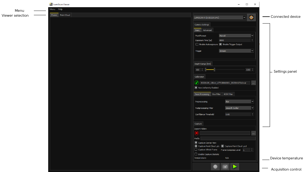
The main window is divided into two sections:
-
The left area (the Viewer) displays the current camera images.
-
The right part is the control panel where you can change the camera settings.
At the top of the display are the two tabs Frame and Point Cloud, which can be used to switch the current output of the Viewer between the LumiScan Viewer and the Point Cloud:
-
The Frame displays the recorded images (frames) from the camera in real time. It is possible to switch between the images of the 13 individual cameras. This display is very useful for setting the exposure time of the camera and for positioning the measurement object.
-
The Point Cloud tab displays the point cloud generated by LumiScan from the 3D image data of the target. The object can be viewed from all sides and the depth parameter settings can be edited and displayed live.
The Menu and Help options are located in the Menu bar.
-
In Menu you will find the entries Save Parameters, Load Parameters, Show log and IP Configuration:
-
With Save Parameters, selected camera settings can be saved for later use.
-
With Load Parameters a previously saved parameter file can be loaded and its configuration settings* applied to LumiScan Viewer. All stored parameters from the selected file are loaded and applied automatically. Supported file formats
.json.ini. -
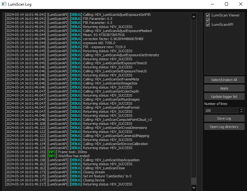
Show log opens the window in which the log is saved. Provides additional information about the processes in the program (LumiScan Log.).
-
IP Configuration allows to configure the IP address settings for your GenICam-compatible camera.
-
-
In the Help option you will find the Show Calibration and About items.
-
Show Calibration provides information about the currently loaded calibration.
-
Under About, you can view the currently installed LumiScan version.
-
|
*The parameters Trigger, TriggerOut and TriggerOutDuration are excluded from loading and will retain their current values. |
At the bottom right of the main window you will find information about the device temperature and acquisition control panel.
Acquisition control contains three buttons:
-
Start capturing: Click this button (green triangle icon) to start continuous capturing and streaming. The button now displays a blue square. Click the button again to stop capturing.
-
Export capture: Clicking on the photo icon saves a single capture of the measurement object.
-
Export capture: (continuous) Clicking on the red recording icon starts the continuous export of captures.
Camera IP Configuration
For stable and high-performance operation, it is strongly recommended to use a Static IP rather than DHCP.
To start the IP Configuration, click Menu → IP Configuration.
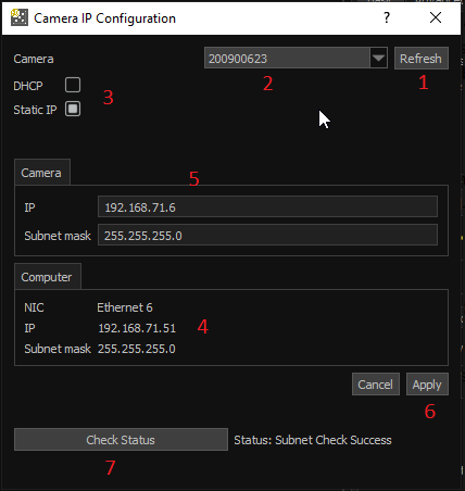
IP Configuration Settings
| Nr | Description |
|---|---|
1 |
The Refresh button is used to search for all cameras currently connected to the network. Before using this function, ensure that the camera is properly connected and powered. When the button is pressed, the application scans the available network interfaces and populates the Camera Selection Dropdown with all detected devices. |
2 |
The Camera Selection Dropdown displays all cameras detected on the network after a refresh. To continue configuration, select the desired camera from the list. Once selected, the camera’s current IP configuration is automatically shown in the fields below. |
3 |
The DHCP / Static IP Options define how the camera receives its network address.
|
4 |
The Computer Network Information section displays the current network configuration of the host PC.
The camera and computer must be located within the same subnet for proper network communication. |
5 |
The Camera Network Settings section allows configuration of the camera’s IP parameters.
Ensure that the camera IP is within the same subnet as the computer but not the same IP. Example:
|
6 |
The Apply button saves the entered network configuration and writes it to the camera. The Cancel button discards any unsaved changes and retains the previous configuration. |
7 |
The Status Check function verifies the connection between the camera and the computer.
|
|
*Always select Static IP for better control and reliability. |
Configuration Steps
Next Configuration Steps are recommended:
-
Connect your camera to the network.
-
Click Refresh to detect the camera.
-
Select the camera from the dropdown list.
-
Enable Static IP and enter your desired IP address.
-
Verify subnet settings to match your computer’s network.
-
Click Apply to save changes.
-
Check Status to confirm successful configuration.
Camera Settings Configuration
To obtain the most accurate point cloud from the LumiScan X depth data, the acquisition parameters must first be set. To simplify the setup, the measurement parameters can be varied during operation.
Camera Settings
The following measurement parameters must be set individually for each measurement object.
At the Camera Setting are the two tabs Basic and Advanced.
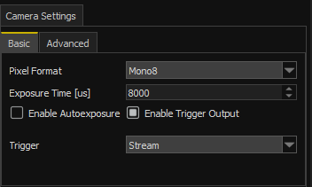
In Basic you will find the entries Parameters (LumiScan Viewer: Camera Settings, Basic):
-
Pixel Format: The pixel format of images captured by the camera.
-
Mono8: Images are captured as 8-bit grayscale images. With 8-bit images, the sensor can capture 6 frames per second (FPS).
-
Mono12: Images are captured as 12-bit grayscale images. With 12-bit images, the frame rate of the sensor is limited to 3 frames per second, but the sensor can provide more accurate results.
-
-
Exposure Time [μs]: The exposure time used to capture the image. Higher values produce brighter images.
-
Enable Autoexposure: This option can be used to automatically set the exposure time.
-
Target Intensity: It is displayed only when Enable Auto Exposure is selected. You can use Target Intensity to adjust the brightness of the image. The higher the value, the brighter the image.
-
Enable Trigger Output: Option to enable the Trigger Out Signal.
-
Trigger: Defines when the camera takes an image:
-
Stream (trigger off): The camera continuously captures new images. Useful for quickly displaying updates in the user interface.
-
Software Trigger: The camera is triggered by the software. To capture an image, you must use the middle button with the photo icon. To enable this button in this option, the valid path must be selected in the Export Folder window in the Capture Panel.
-
Hardware Trigger: The capture will be triggered by an external line. This option should be used when using a process control device (PLC). This mode is also useful when external devices, such as sample projectors, are to be triggered simultaneously.
-
If you select the Hardware Trigger option, additional options are displayed: Trigger Edge and Trigger Delay.
-
Trigger Edge: This is the time the image was taken. There are two possibilities:
-
Falling Edge: The image is captured when the signal drops out.
-
Rising Edge: The image is captured when the signal rises.
-
-
Trigger Delay [μs]: The trigger signal is sent to the camera, which waits a certain amount of time before it starts recording.
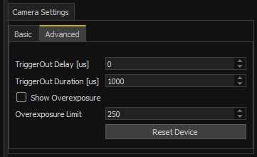
In Advanced you will find the entries Parameters (LumiScan Viewer: Camera Settings, Advanced):
-
TriggerOut Delay [μs]: Defines the time interval between the internal trigger event of the LumiScan X and the activation of the external trigger output signal.
-
TriggerOut Duration [μs]: Defines the duration of the high-level output signal.
-
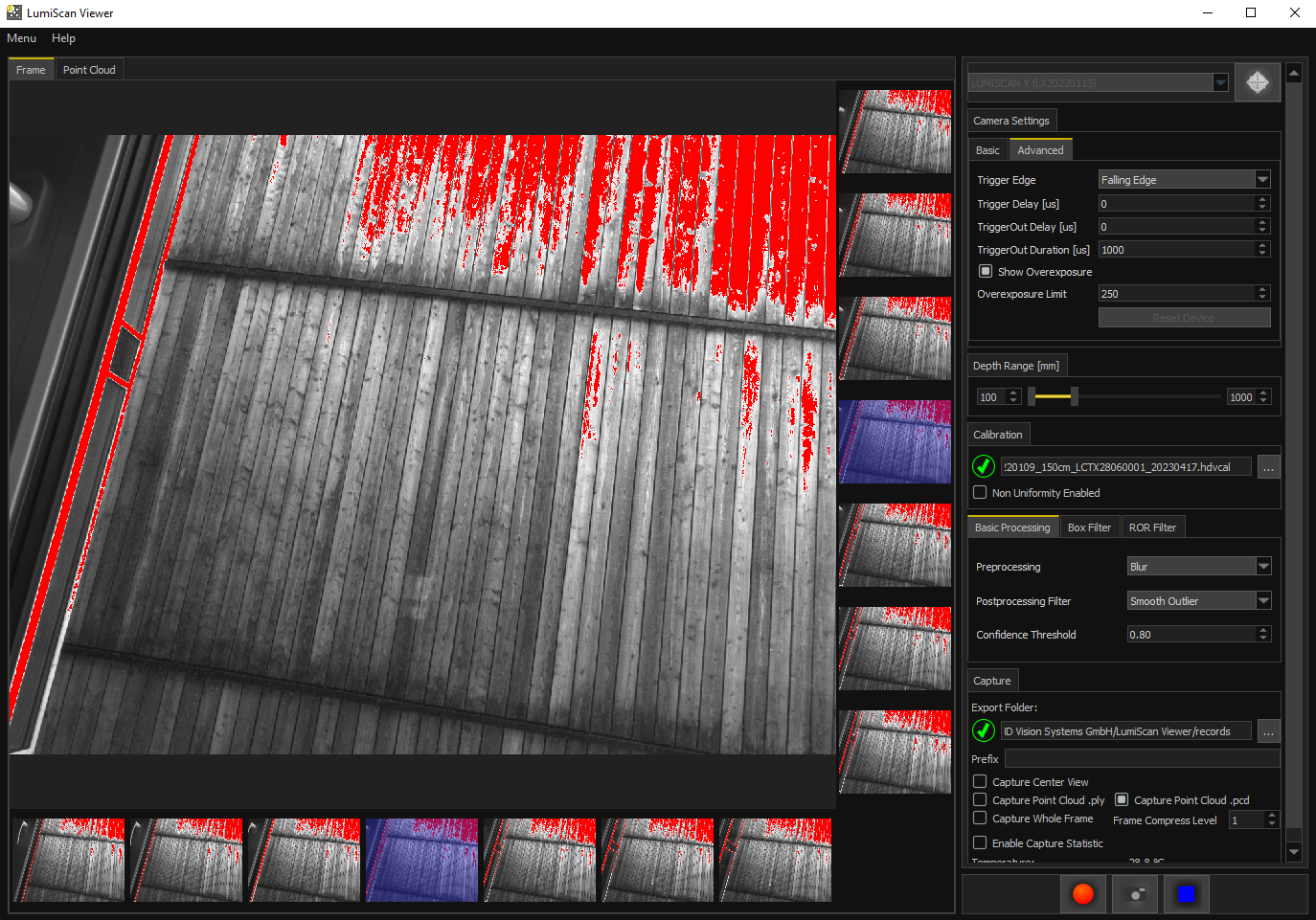
Show Overexposure: When enabled, this feature highlights overexposed pixels in the image display. Each pixel value is compared to the configured Overexposure Limit.
-
If a pixel’s intensity exceeds the defined threshold, the pixel is rendered in red to visually indicate overexposure (LumiScan Viewer: Overexposure Example).
-
Pixels with intensity values below or equal to the threshold are displayed normally.
-
-
Overexposure Limit: Defines the maximum allowable pixel intensity before it is considered overexposed. The parameter can be set within a range from 0 (black) to 255 (white)*.
|
*When the MONO12 pixel format is used, pixel intensity values are represented in the range 0–4095. For comparison with the Overexposure Limit, these values are linearly scaled to the range 0–255. This scaling ensures consistent threshold behavior across different image formats. |
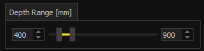
Depth Range
The depth range in millimeters used for the calculation. All calculated values will be within this range. The size of the measurement range has a direct effect on performance. Therefore, setting the depth range to the actual position of the measurement object can significantly improve performance.
Calibration
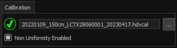
Enter the location of the calibration file (.hdvcal). By default, the calibration files are stored in the following path:
C:\ProgramData\HD Vision Systems GmbH\calibration.
-
Non Uniformity: Enabling this option improves image quality by compensating for differences in object lighting. Enabling this option requires a separate file in the calibration window. This file can be found in the calibration folder.
Processing
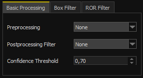
The processing area consists of three tabs: Basic Processing, Box Filter and ROR Filter.
The following options can be set in the Basic Processing tab (LumiScan Viewer: Basic Processing):
-
Preprocessing: Configures the filter to use for preprocessing:
-
None: The captured images are used directly for the calculation.
-
Blur: Smoothes the image data before processing (low-pass filter).
-
-
Postprocessing Filter: Configures the postprocessing filter applied to the resulting depth information:
-
None: No filter is applied
-
Median filter: A median filter is applied to smooth the results. This reduces the noise in the data. However, edges in the resulting geometry are also smoothed, which may not be desirable.
-
Smooth Outlier: This option also applies a median filter. Compared to the Median Filter option, the data is smoothed to a greater extent.
-
-
Confidence Threshold: This numerical cutoff value (0.0-1.0) is used to filter out low-quality or uncertain data points. A higher confidence threshold eliminates outlier points.
In the Box Filter, the parameters of the box filter can be set (LumiScan Viewer: Box Filter).
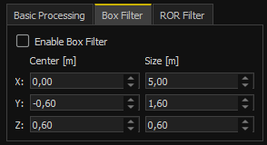
This filter removes all points from the resulting point cloud that do not lie within the specified cuboid box.
The center and extent of the box can be set for the X, Y and Z axes. The coordinate system used is identical to that output by the LumiScan X. The camera is located at the origin of the coordinates and is aligned in the direction of the Z-axis. The unit of the coordinate system is meters.
In ROR Filter, the parameters of the Radius Outlier Removal Filter can be set. (LumiScan Viewer: ROR Filter).
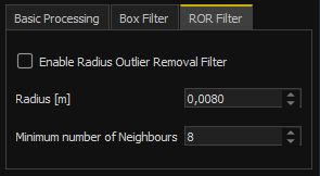
This filter removes all points from the resulting point cloud that have too few other points in their vicinity. The following parameters can be set for the filter:
-
Minimum number of neighbors: Specifies how many neighboring points must be around a point.
-
Radius: Defines the maximum distance between the neighboring points and the point in question.
The radius used is specified in meters.
Image Capture
Once all measurement parameters are set, the camera’s recording function can be activated:
-
Click the start capturing button (green triangle icon).
-
The recorded camera image then appears in the LumiScan Viewer (frame display).
-
You can switch between the individual cameras of the LumiScan X system by clicking on one of the thirteen preview images at the edge of the viewer.
-
The image from the selected camera is displayed in the main area of the Viewer.
-
The display can be zoomed by scrolling with the mouse wheel.
-
To move the image to the desired position, click and hold the left mouse button.
-
Point Cloud Viewer
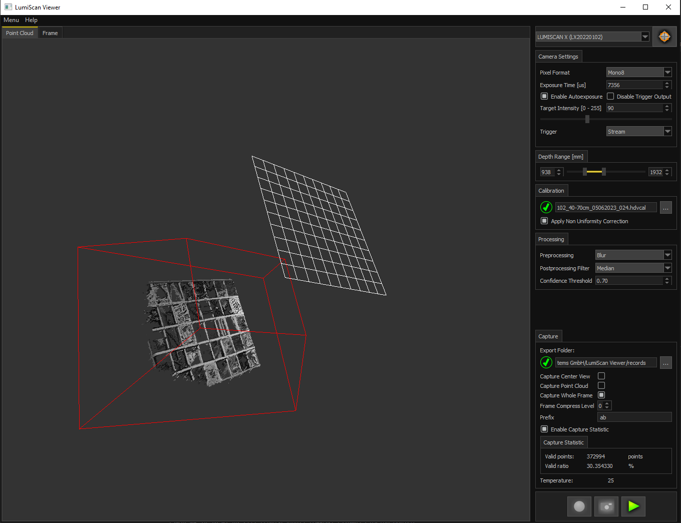
Switch to the Point Cloud tab to display the calculated point cloud of the measurement object (The Point Cloud Viewer for viewing captured 3D point clouds.).
By default, you will first see a plane represented by a white grid. This is the camera plane, i.e. the origin of the light field.
Behind this plane is the three-dimensional structure of the target, which is made up of individual measuring points.
Together, these points form the point cloud of the captured object.
You can use the Point Cloud Viewer to view these points in detail:
-
The view can be zoomed in and out by scrolling the mouse wheel.
-
If you hold down the left mouse button and move the mouse pointer, you can rotate the display around this point.
-
By holding down the right mouse button, you can move the image horizontally and vertically.
Data Export
You can set the desired data export settings in the Settings Panel under Capture:
-
Export Folder: Enter the desired export path. The default export path is:
C:\Users\Username\HDVisionSystems\LumiScan\export. -
Capture Center View: Select this option if you want to export the image from the center camera.
-
Capture .ply/.pcd Point Cloud: Select this option if you want to export the point cloud in ply or pcd format. Both options can be set independently.
-
Capture Whole Frame: Select this option if you want to save all raw data - 13 individual images per frame (high storage space requirement).
-
Frame Compress Level: An option to compress an image to reduce memory requirements without losing quality. When this option is enabled, saving and exporting data takes longer.
-
Prefix: By default, each exported file is saved with the date and time in the filename. If you want to use a specific prefix in the file name for a measurement series, you can specify it here.

-
Enable Capture Statistics: Enabling this option displays capture statistics.
-
Capture Statistic: Here you will find information about the Valid Points and the Valid Ratio.
-
The recorded data can be exported. There are two options:
-
Export single capture: Click the photo icon to export a single capture of the measurement object.
-
Export recording: (continuous) Clicking the Record icon starts the continuous export of the captures. Each frame captures is saved; at 6 FPS, this is equivalent to 360 frames per minute.
Click the Record icon again to stop the export.
|
This option uses a lot of memory when recording over a long period of time. |
Software Update
For software updates, you will receive a link to the website and a protected access password (Software Update: Protected access password).
-
After entering your password, you will be redirected to the update download page.
-
Download the update to your computer.
-
Click on the downloaded file.
-
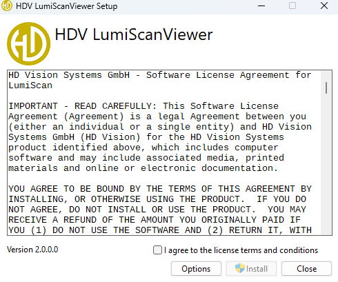
A dialog box appears (Installation dialog box).
-
Click on the Install button.
-
Installing the update is similar to the initial installation (see chapter Installing the Software).
-
If an error occurs, the software should be uninstalled and reinstalled (see An error occurs while installing a software update).
-