Product Description
LumiScan X enables the LumiScan technology of 13 discrete 1.2 MPix cameras. Its use is optimized for robotics, automation, and quality inspection.
How the light field technology of the LumiScan X works is explained in Technology.
Each LumiScan X camera has its own unique number (e.g. LX20230101). This number can be found on the back of the camera housing.
Measurement distances and measurement volumes can be varied over a wide range. Optimum results are achieved with measurement distances of 250 - 3000mm and measurement volumes of 200 - 3360mm, depending on configuration.
LumiScan X Technical Specifications
LumiScan X cameras are available in three versions depending on the angle of view: 60, 40 and 30:
| Camera Variant | X | Y |
|---|---|---|
LumiScan X60 |
60° |
45° |
LumiScan X40 |
40° |
35° |
LumiScan X30 |
30° |
20° |
Camera Housing Dimensions
| Specification | LumiScan X |
|---|---|
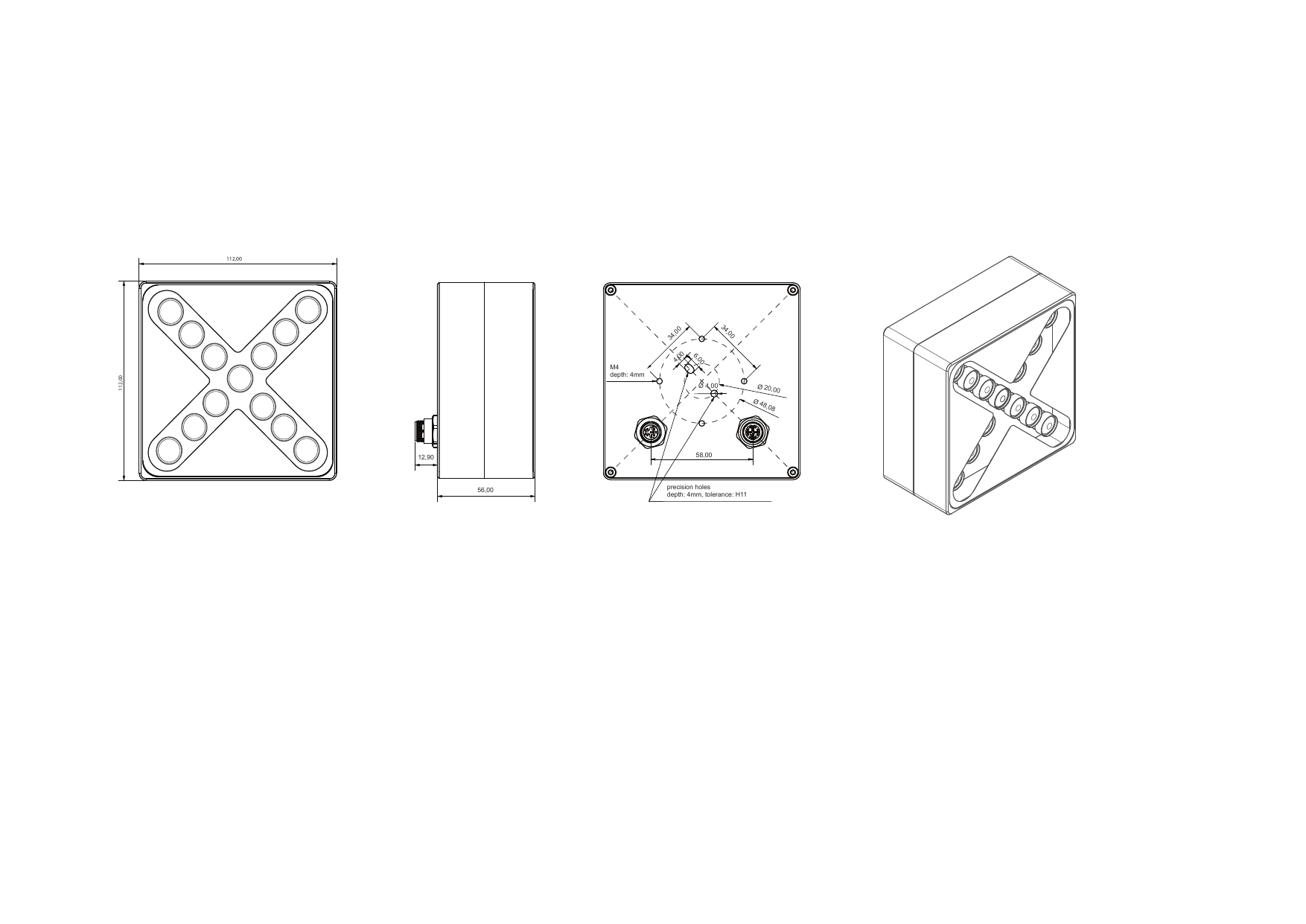
Casing dimensions: |
112 mm × 112 mm × 56 mm |
Weight: |
737 g |
Protection: |
IP54 |
Threads: |
M4 screws, Depth: 4 mm |
The camera is mounted using four M4 threaded holes. The maximum thread depth is 4 mm.
The precision holes are optional and can be used for more precise positioning of the camera.
Sensor Technical Specifications
| Specification | LumiScan X |
|---|---|
Resolution (depth map) |
1.2 MP (1280 × 960) |
Point-to-point distance |
0.84 mm (at 1 m edge measurement field) |
Calibration accuracy |
≤ 0.50 mm (at 1 m edge measurement field) |
Temporal Z noise |
≤ 0.50 mm (at 1 m edge measurement field) |
Maximum frame rate |
6 fps |
Single Capture / Snapshot |
1000 µs |
Acquisition time (object detection) |
1 s |
Recommended measuring distance |
250 - 3000 mm |
3D point throughput |
7.2 million points per second |
Camera-array |
13 × 1.2 MPix, Monochrome, 12 Bit |
Sensor Electrical Specifications
| Specification | LumiScan X |
|---|---|
Power supply |
24 V DC or PoE (IEEE 802.3af) |
Power consumption (typical) |
5.5 W |
Standard Configurations
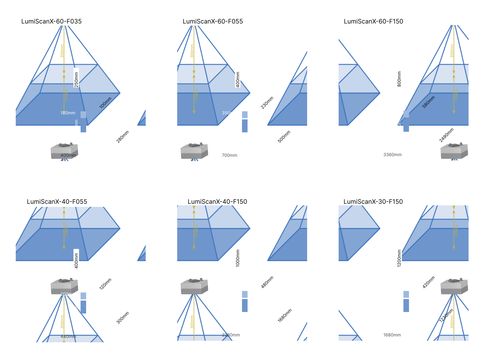
To simplify the manufacturing process, standards are defined for the focus and calibration distances that are used most frequently.
| Configuration | Lens focal length | Set focus | In-focus range | Standard calibration range | Field of view at minimum working distance | Field of view at maximum working distance |
|---|---|---|---|---|---|---|
LumiScanX-60-F035 |
4.14 mm |
350 mm |
approx. 250 mm - 450 mm |
250 mm - 450 mm |
approx. 180 mm x 100 mm |
approx. 400 mm x 280 mm |
LumiScanX-60-F055 |
4.14 mm |
550 mm |
approx. 400 mm - 700 mm |
400 mm - 700 mm |
approx. 350 mm x 230 mm |
approx. 700 mm x 500 mm |
LumiScanX-60-F150 |
4.14 mm |
1500 mm |
800 mm - infinity |
800 mm - 3000 mm |
approx. 810 mm x 580 mm |
approx. 3360 mm x 2490 mm |
LumiScanX-40-F055 |
6 mm |
550 mm |
approx. 400 mm - 700 mm |
400 mm - 700 mm |
approx. 200 mm x 120 mm |
approx. 440 mm x 300 mm |
LumiScanX-40-F150 |
6 mm |
1500 mm |
1000 mm - infinity |
1000 mm - 3000 mm |
approx. 680 mm x 480 mm |
approx. 2280 mm x 1680 mm |
LumiScanX-30-F150 |
8 mm |
1500 mm |
1200 mm - infinity |
1200 mm - 3000 mm |
approx. 600 mm x 420 mm |
approx. 1680 mm x 1230 mm |
Power Supply
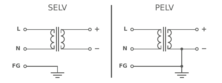
For the power supply of the LumiScan X, we recommend using a Safety Extra-Low Voltage (SELV) supply.
If this is not feasible, a Protective Extra-Low Voltage (PELV) supply with safe electrical isolation may also be used. In this case, however, it is essential that all grounding conductors are connected to a common star grounding point.
Failure to follow this requirement may result in unwanted leakage or compensating currents and sensor malfunctions.
The difference between SELV and PELV supplies is illustrated in Comparison of SELV and PELV power supplies.
Pin Assignment IO-Link & Power
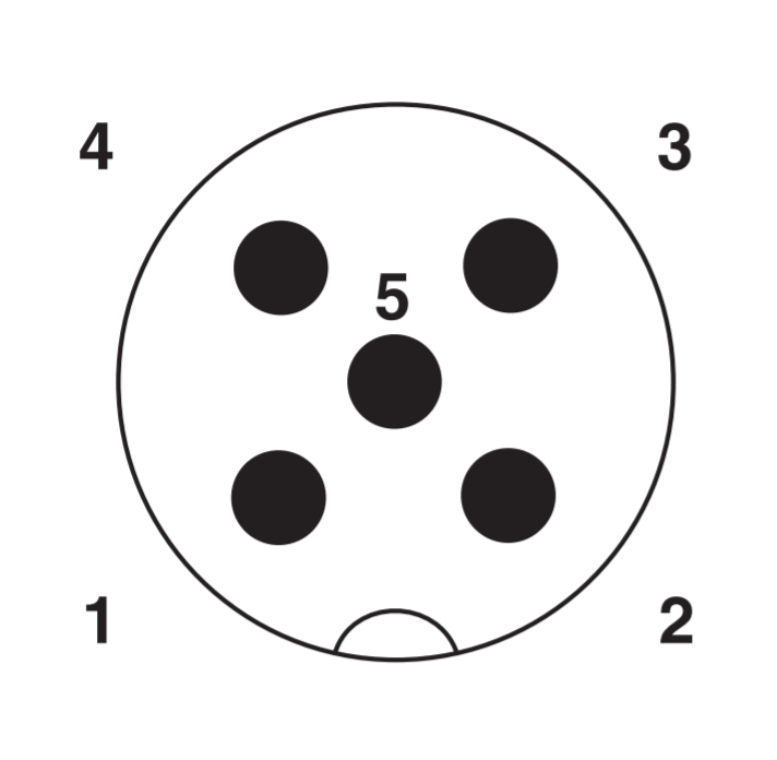
| Pin | Assignment |
|---|---|
Pin 1 (brown) |
Sensor 24 V |
Pin 2 (white) |
Trigger GND |
Pin 3 (blue) |
Sensor GND |
Pin 4 (black) |
Trigger IN |
Pin 5 |
Trigger OUT |
Trigger In Signal
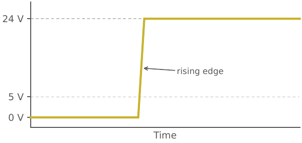
The LumiScan X can be used in Hardware Trigger Mode using an external trigger signal to capture images. This trigger signal has to fulfill the following requirements:
-
minimum voltage high level: 5V
-
optimum voltage high level: 24V
-
minimum signal length: depends on internal resistance of source (up to 5 milliseconds)
Trigger Out Signal
The Trigger Out signal can be used to connect a flash light such as the pattern projector LumiScan SL. The signal output is an open collector and has no voltage potential. To generate a voltage to trigger the light, the output must be wired with a pull-up resistor (Schematic diagram of the LumiScan X connection with a pull-up resistor to generate the voltage for the trigger output.).
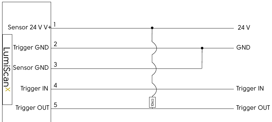
The LumiScan SL is supplied with the necessary resistor and can be connected to the LumiScan X as described in the LumiScan SL’s manual.
The Trigger Output of the LumiScan X can be used to trigger other hardware (e.g. flashlights like the LumiScan SL) simultaneously. To activate the trigger output, the parameter "line source" needs to be set to "timer1active". In the newest version of our SDK this is set automatically when a LumiScan X is connected.
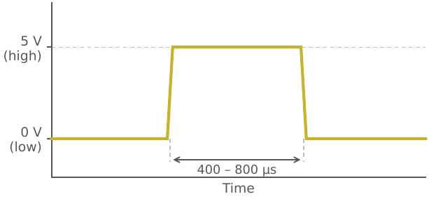
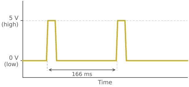
The output signal using a pull-up resistor has the following characteristics:
-
High-level signal duration: 400 – 800 µs
-
High level: approx. 5 V
-
Low level: approx. 0 V
-
Time between trigger signals (in stream mode): 166 ms
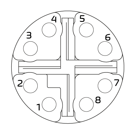
Pin Assignment of Ethernet Connection
Electrical and mechanical specifications are based on a properly mated connector pair.
| Specification | Ethernet Connection |
|---|---|
Signal category: |
CAT6A |
Number of pins: |
8 |
Current rating: |
500 mA |
Supply voltage: |
24 V DC |
Rated pulse voltage: |
1.5 kV |
Contact resistance: |
20 mΩ |
Type description: |
SACC-CI-M12FSX-8P SMD SH T |
| Pin | Color Coding |
|---|---|
1 |
white/orange |
2 |
orange |
3 |
white/green |
4 |
green |
5 |
white/brown |
6 |
brown |
7 |
white/blue |
8 |
blue |
Ethernet Cable Characteristics
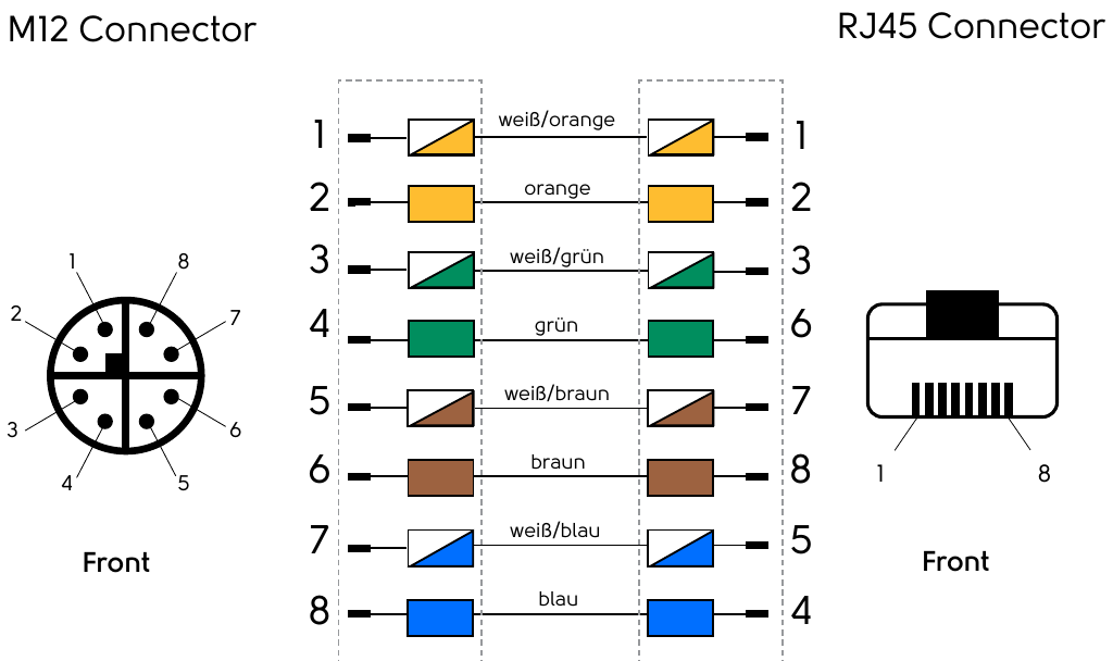
A CAT6A Ethernet cable with an M12 connector (LumiScan X side) to RJ45 connector (computer side) is required to properly connect the LumiScan X (see Hardware Requirements).
The connection diagram for the two connectors is shown in Connection diagram for M12 and RJ45 connectors in the Ethernet cable..
For connecting the camera, the use of cables from Phoenix Contact GmbH & Co. KG is recommended.
-
For angled connectors: Part number 1295151
-
For straight connectors: Part number 1408647
The connector must be tightened to a torque of 0.4 Nm to ensure a secure and reliable connection.
The appropriate tool is available from Phoenix Contact under part number 1208432.
|
When using cables from other manufacturers, the connector dimensions must be carefully observed. Larger connectors may cause damage to the LumiScan X. |
Hardware Requirements
-
LumiScan X camera system
-
Power supply unit (24 V DC)
-
Ethernet cable CAT6A, S/FTP shielded, M12 male to RJ45 male, TIA-568B variant
-
Sensor/actuator cable, 5-pin, free cable end to M12 socket
-
Computer with following minimum configuration:
-
Processor: Intel i5 2.4 GHz or better
-
RAM: 8 GB
-
Graphics card: NVIDIA GTX 1650 or better
-
Network: Intel Ethernet Adapter I210 or better
-