Light Field Acquisition Architectures
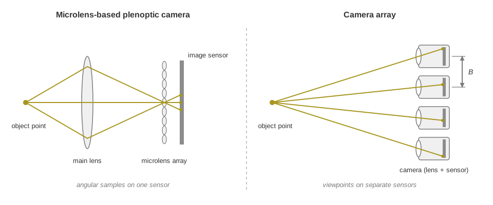
All light field cameras are based on the same physical principles (see Light Field Imaging), but they acquire the spatial and angular information in different ways. The two main approaches are microlens-based plenoptic cameras and camera arrays (Microlens-based plenoptic camera (left): the rays from one object point reach different pixels behind one microlens. Camera array (right): each camera records the object point from its own viewpoint; B is the baseline between two cameras.). Both sample the four-dimensional light field; they differ in their optical construction, in the geometry of their angular sampling and in how they use the resolution of their image sensors.
Microlens-Based Plenoptic Cameras
A microlens-based plenoptic camera consists of a main lens, a microlens array and an image sensor. The main lens collects the light from the scene. The microlens array between the main lens and the sensor separates the light by position and direction, so the sensor records a structured image that contains several angular observations of the scene. From this image, algorithms derive sub-aperture images, estimate depth and synthesize images with different focus settings.
Plenoptic 1.0
In the classical plenoptic camera, often called plenoptic 1.0 (see Ng et al., 2005), the microlens array is placed near the image plane of the main lens, and each microlens forms an image of the main lens aperture on the sensor. The pixels behind one microlens therefore correspond to different directions of propagation. This yields angular information at the expense of spatial resolution: on a sensor with a fixed number of pixels, more angular samples leave fewer independent spatial samples.
Focused Plenoptic Cameras (Plenoptic 2.0)
In the focused plenoptic camera, also called plenoptic 2.0 (Lumsdaine and Georgiev, 2009), the microlenses are focused on the intermediate image formed by the main lens instead of on its aperture. This distributes the spatial and angular information differently and can give a comparatively high effective spatial resolution while keeping angular information for depth reconstruction and digital refocusing. Some designs combine microlenses with different focal lengths to extend the usable depth range.
Microlens-based cameras are used in industry where a compact system, short working distances and 3D information from a single optical assembly and a single exposure are important, for example in close-range inspection.
Camera Arrays
A camera array acquires the light field with several physically separated cameras, each with its own optics and image sensor. The cameras observe the scene from different positions and thus sample the light field over a spatially distributed set of viewpoints. The angular information comes from the physical separation of the cameras, not from a microlens array, and each camera records a conventional image at the native resolution of its sensor.
Light Field Sampling
An array of \(N\) cameras records the images
where \(I_i\) is the image of camera \(i\). Each camera has a known position and orientation in a common coordinate system. With the intrinsic and extrinsic calibration parameters, every pixel can be assigned to a ray in three-dimensional space, and all these rays together form a discrete sample of the four-dimensional light field. For a regular, rectified camera array, this can be written as:
Here \((u_i, v_i)\) is the viewpoint of camera \(i\) and \((s, t)\) are the coordinates in a common image parameterization. The number and arrangement of the cameras determine the angular sampling; the image sensors and optics determine the spatial sampling.
Advantages of Camera Arrays
- Independent spatial sampling
-
Each camera records an image at its native sensor resolution. The angular information comes from additional viewpoints, not from dividing one sensor into spatial and angular samples.
- Selectable baseline
-
The distance between the viewpoints is set by the physical arrangement of the cameras and can be chosen to suit the working distance and the depth requirements.
- Multiple observation directions
-
A surface that is hidden from one camera may be visible from another, which gives additional opportunities to observe and reconstruct the scene geometry.
- Configurable optics
-
The lenses and the array geometry can be chosen for different measurement volumes and fields of view.
Engineering Considerations
Camera arrays also bring challenges:
-
Accurate 3D reconstruction requires precise knowledge of the relative positions and orientations of all cameras.
-
The cameras must expose synchronously, particularly when objects move. LumiScan X exposes all 13 cameras at the same time (see Multi-Camera Image Acquisition).
-
The algorithms must find corresponding features in images that can differ considerably because of parallax, occlusions and viewpoint-dependent reflections.
-
With more cameras, the amount of image data and the computing effort generally increase.
The design of a camera array therefore balances geometric accuracy, spatial resolution, angular sampling, computing effort and acquisition speed.
Comparing the Two Architectures
The main difference between microlens-based plenoptic cameras and camera arrays is the scale and geometry of their angular sampling (Microlens-based plenoptic camera and camera array compared).
| Characteristic | Microlens-based plenoptic camera | Camera array |
|---|---|---|
Optical configuration |
Main lens and microlens array |
Several cameras with individual lenses |
Image sensors |
Typically one |
Several |
Angular sampling |
Within one optical system |
Across physically separated viewpoints |
Baseline |
Limited by the optical design and the entrance pupil |
Defined by the camera positions |
Spatial resolution |
Shared with the angular sampling on one sensor |
Native resolution of each camera |
Calibration |
Main lens and microlens geometry |
Individual cameras and their relative poses |
Synchronization |
Inherent in the single exposure |
Requires coordinated acquisition |
System size |
Potentially very compact |
Depends on the camera arrangement |
Reconstruction |
Plenoptic disparity and other light field methods |
Multi-view correspondence and triangulation |
Neither architecture is better in general. Microlens-based plenoptic cameras offer compact optics, dense angular sampling within a limited aperture and effective solutions for close-range inspection. Camera arrays offer more freedom in the choice of the physical baseline, the camera arrangement and the spatial resolution. The most suitable architecture depends on the application.
Architectural Trade-offs
Baseline and Depth Sensitivity
The baseline is the effective distance between the viewpoints used for triangulation. For an ideal rectified stereo configuration with \(Z = f B / d\) (see Parallax, Disparity and Depth), an uncertainty \(\sigma_d\) of the estimated disparity causes a depth uncertainty of approximately (to first order):
Two properties follow. First, for a fixed baseline, focal length and disparity uncertainty, the depth uncertainty grows approximately with the square of the distance. Second, a longer baseline can reduce the depth uncertainty. However, a longer baseline also increases the differences between the viewpoints, which makes correspondence estimation more difficult and introduces additional occlusions. The best baseline therefore depends on the measurement volume, the object geometry, the surface properties and the reconstruction method.
| This relationship is not a complete accuracy model. The actual measurement uncertainty also includes calibration, optical, matching and systematic effects. |
Spatial and Angular Resolution
Microlens-based plenoptic cameras record spatial and angular information on one sensor, so their effective spatial resolution depends on how the pixels are divided between these dimensions. Camera arrays record the spatial information on several sensors. This avoids the single-sensor trade-off, but adds cameras, data transfer and reconstruction effort.
The total number of sensor pixels of a camera array does not directly determine the spatial resolution of its depth map. The effective 3D resolution depends on the reconstruction method, the scene texture, the camera geometry and the visibility of corresponding features.
Occlusions
An occlusion occurs when a surface is hidden by another object from a particular viewpoint. Because a light field camera observes the scene from several directions, it can recover information that a single viewpoint does not provide. How well it resolves occlusions depends on the angular extent and the distribution of the viewpoints: a wider angular range reveals more surfaces, but can make it more difficult to match corresponding features.
Reflective and Textureless Surfaces
Depth estimation based on image correspondence becomes difficult when surfaces lack distinctive image features. Specular surfaces, in addition, look different from different viewpoints. The additional observations of a light field help the reconstruction algorithms check geometric consistency across the viewpoints, but angular sampling alone does not guarantee a reliable reconstruction of reflective or textureless surfaces. A pattern projected onto a textureless surface gives it an artificial texture in which correspondences can be found; LumiScan X uses the pattern projector LumiScan SL for this (see Passive 3D Imaging and Illumination). The result depends on the illumination, the optical configuration, the surface properties and the algorithms.