User Interface

By default, the user interface contains the Image tab, status information, and the Manual Mode button (Fig. 4).

The purple rectangle indicates the region of interest (ROI). It defines the area of the captured image in which the network searches for objects.

When debug mode is enabled, a yellow auto-exposure polygon is also displayed (Fig. 5). This is useful when configuring the initial exposure parameters.
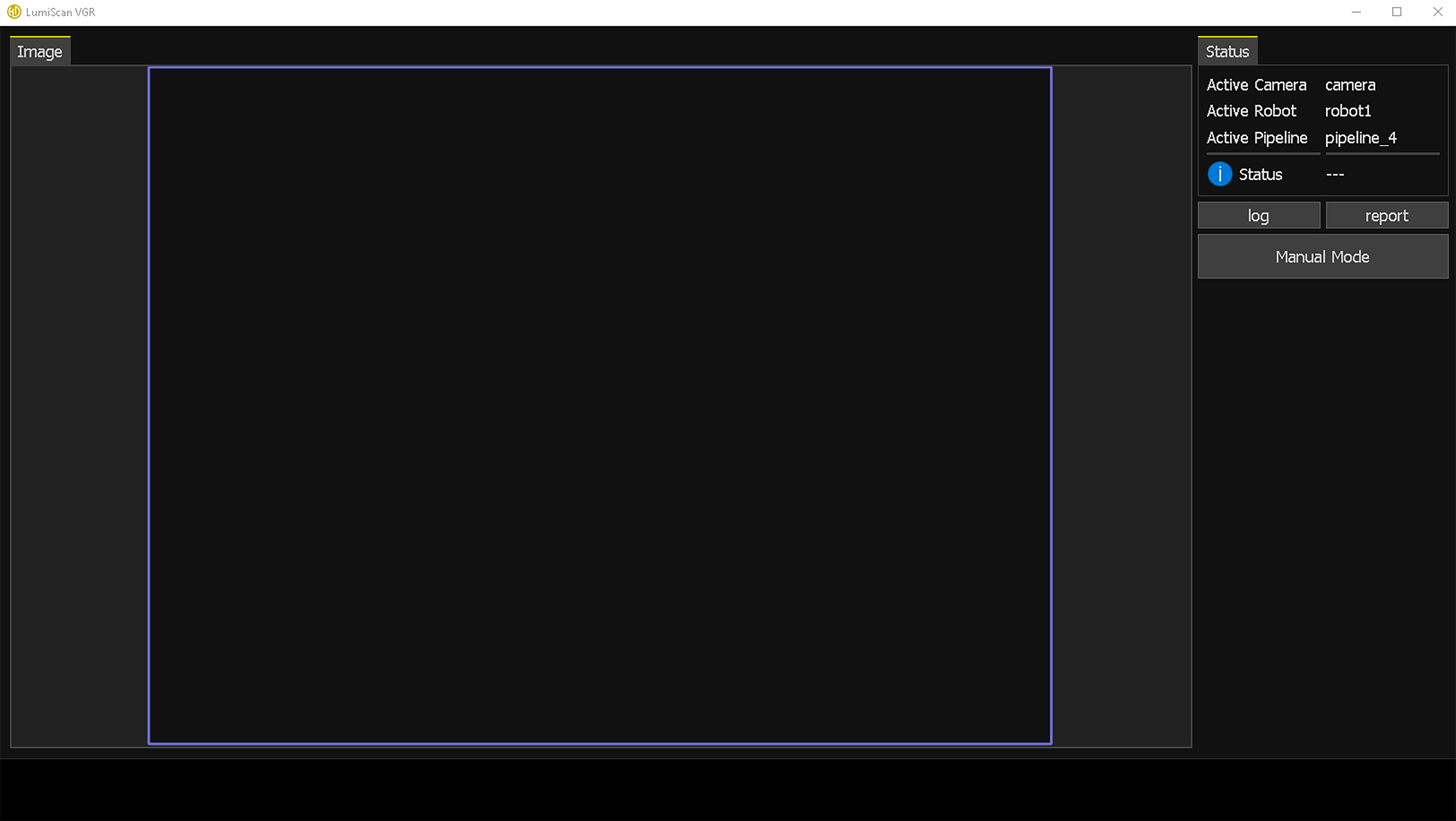
LumiScan VGR user interface with the Image tab, status information, and Manual Mode controls

For a detailed description of the user interface, see Fig. 6 and Table 4.
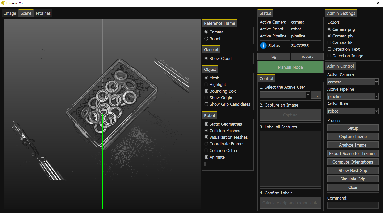
LumiScan VGR user interface showing a captured image, detected objects, status information, and manual and administrative controls
Table 1. Table 4: LumiScan VGR User Interface Elements
Element Description

T0

Image Tab

Displays the image from the active camera together with the current object detection results.

  • In manual mode, object bounding boxes can be drawn and modified in this view.

T1

Scene Tab (Fig. 9)

Displays 3D information about the scene and the calculated grip points for detected objects.

The view can be controlled using the mouse:

  • Scroll with the middle mouse button to zoom in or out.

  • Hold the middle mouse button and move the mouse to rotate the view.

  • Hold Shift and the middle mouse button while moving the mouse to move the displayed section.

Opening this tab displays additional Scene controls (Sc1 to Sc6).

T2

PROFINET Tab (Fig. 10)

Displays the current data exchanged with the PLC.

S1

Displays general status information.

S2

Displays the current application status. See Table 6: Return Values for more information.

S3

Opens the log window, which provides additional information about processes and events in the application.

S4

Collects diagnostic information about the application.

  • The collected data can be encrypted and sent to HD Vision Systems for diagnostic purposes.

  • The Camera png and Camera ply options under Export in Admin Settings (A1) must be enabled to include the corresponding camera data.

M1

Activates manual mode. See Manual Mode.

M2

Contains the controls available in manual mode. See Manual Mode.

M3

Step 1 of the manual workflow: Select a user.

  • A user must be selected before continuing.

  • New users can be added using the …​ button.

  • The selected user is stored as metadata when new training data is exported.

  • Only visible in manual mode.

M4

Step 2 of the manual workflow: Capture and analyze an image.

  • Captures a new image and detects objects.

  • Detected objects can then be corrected, and missing objects can be labeled using the labels in M5.

  • The function can be executed multiple times.

  • Only visible in manual mode.

M5

Step 3 of the manual workflow: Select a label.

  • Contains all available object labels.

  • The selected label is used when creating new bounding boxes in the Image tab (T0).

  • Only visible in manual mode.

M6

Step 4 of the manual workflow: Complete the operation.

If the image is labeled correctly, click DONE. A confirmation message indicates that the training data has been exported and the grip points have been calculated.

If no grip points can be calculated because the 3D information is invalid, for example because of a poor point cloud or incorrect configuration, the status changes to RESULTS_EMPTY. No confirmation is displayed and no training data is exported.

  • Training data is exported to the training data output folder. See Generated Data and Files.

  • Only visible in manual mode.

A1

Admin Settings

Contains options for enabling and disabling data export.

  • Settings can be changed while the application is running.

  • The available output may differ when debug mode is enabled. See Admin and Debug Modes.

  • Only visible in admin mode.

A2

Admin Controls

Contains controls for manually executing individual application functions.

  • Only visible in admin mode.

  • Only active in manual mode to ensure that the automatic process is paused.

A3

Changes the active camera.

  • Only visible in admin mode.

  • Only active in manual mode.

A4

Changes the active pipeline.

  • Only visible in admin mode.

  • Only active in manual mode.

A5

Changes the active robot.

  • Only visible in admin mode.

  • Only active in manual mode.

A6

Initializes the application.

Initialization is required before functions A7 to A13 can be used.

  • Only visible in admin mode.

  • Only active in manual mode.

A7

Captures an image using the active camera.

  • Only visible in admin mode.

  • Only active in manual mode.

A8

Analyzes the most recently captured image using the active pipeline.

  • Only visible in admin mode.

  • Only active in manual mode.

A9

Exports the currently labeled image as training data.

  • Only visible in admin mode.

  • Only active in manual mode.

A10

Calculates the pose of all detected objects in the currently labeled image.

  • Only visible in admin mode.

  • Only active in manual mode.

A11

Highlights the object with the highest grip priority.

  • Only visible in admin mode.

  • Only active in manual mode.

A12

Simulates the robot gripping the object with the highest grip priority.

The corresponding bounding box is removed from the Image tab (T0), and the position is stored as the most recent grip position.

  • Only visible in admin mode.

  • Only active in manual mode.

A13

Clears all internal buffers.

  • Only visible in admin mode.

  • Only active in manual mode.

A14

Executes user-defined commands.

  • Only visible in admin mode.

  • Only active in manual mode.

Sc1

Scene Settings

Contains the controls for configuring the Scene tab.

  • Only visible in admin mode.

Sc2

Reference Frame

Selects the reference frame used to display the scene.

Available reference frames include:

  • Camera

  • Robot

  • Only visible in admin mode.

Sc3

General

  • Show Cloud: Displays the generated point cloud.

  • Only visible in admin mode.

Sc4

Object

Contains visualization options for detected objects.

  • Mesh: Displays the CAD model generated from the point cloud.

  • Highlight: Highlights in red the point cloud points used for object matching.
    Show Cloud (Sc3) must be disabled to use this option.

  • Bounding Box: Displays the bounding box of each object in yellow.

  • Show Origin: Displays the coordinate frame of each detected object.

  • Show Grip Candidates: Displays the available grip candidates.
    Show Origin must be disabled to display them.

  • Only visible in admin mode.

Sc5

Robot

Contains visualization options for the robot and its environment.

  • Static Geometries: Displays static elements in the robot environment. This option is available when Collision Meshes or Visualization Meshes are enabled.

  • Collision Meshes: Displays simplified robot geometry used for collision detection. Available only after Show Best Grip (A11) has been executed.

  • Visualization Meshes: Displays the robot visualization model. Available only after Show Best Grip (A11) has been executed.

  • Coordinate Frames: Displays the robot coordinate frames.

  • Collision Octree: Displays information used to evaluate potential collisions during robot movement.

  • Animate: Automatically simulates the robot movement. This option is available after Show Best Grip (A11) or Simulate Grip (A12) has been executed.

  • Only visible in admin mode.

Sc6

Moves the robot arm through the simulated motion.
This option is available after Show Best Grip (A11) or Simulate Grip (A12) has been executed and when Animate is disabled.

Manual mode requires the application to be initialized, for example by executing Setup in admin mode or from the PLC. If the application has not been initialized, the camera may not be recognized and no images can be captured.